Categories
- Pipe & Tube (18)
- Flange & Fitting (97)
- Fastener & Gasket (12)
- Valve & Pump (18)
- Base Material (11)
- Equipment (8)
- Application (30)
- Technical (110)
Shijiazhuang Metalsin supplies a full range of socket welding flanges manufactured to ASME B16.5 in pressure ratings of Class 150, Class 300, Class 600 and Class 1500. According to ASME B16.5, socket weld flanges (SW) are available in sizes from 1/2″ to 3″ for all pressure ratings except Class 1500 which is available in sizes from 1/2″ to 2-1/2″.

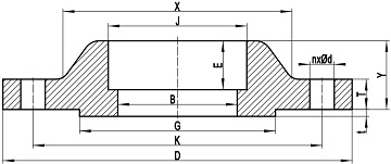
Fig-1: a typical drawing of socket welding flange conforming to ASME B16.5 with raised face.
The socket welding flange conforming to ASME B16.5 is also a hubbed flange, which is generally constructed of a circular flange body and a tapered hub. The flange shall be manufactured as one piece and the taper shall not exceed 7 degrees. A socket structure of a certain depth shall be machined out in the bore. The diameter of socket (counterbore, dimension J as illustrated in Fig-1) shall be the same as that of the slip on flange of same size. Diameter of the smaller bore (dimension B) shall be equal to the nominal inside diameter of adjoining pipe or the bore diameter of welding neck flange of same size. The socket welding flange can be furnished with raised face (RF), flat face (FF), or ring type joint (RTJ).

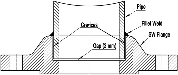
Fig-2: illustration of the welding of a socket welding flange to a pipe.
Socket welding flange is welded to a pipe by a circumferential fillet weld, which joins the outside surface of the pipe and the hub of the flange. The fillet weld is a weld of an approximately triangular cross section joining two surfaces approximately at right angles to each other. The pipe is inserted into the socket of the flange first and alignment is relatively simple since the pipe fits into the socket readily. A 1/16″ (2.0 mm) gap shall be maintained prior to welding between the pipe end and the socket bottom of the flange. This gap is furnished to allow for differential thermal expansion of the mating elements. If there is no gap, when temperature increases, the thermal expansion difference between the pipe and the socket weld flange may result in cracking of the fillet weld. An internal weld is sometimes employed for added strength. By grinding the internal weld smooth, turbulence and flow restriction are kept to a minimum.
Socket welding flanges conforming to ASME B16.5 are permitted under the B31 series of Pressure Piping Codes and ASME Boiler and Pressure Vessel Codes. In piping engineering, although available in sizes up to 3″, they are most frequently used in sizes 2″ and smaller. Thus, socket welding flanges shall be applied for small diameter high-pressure piping systems. A significant disadvantage of socket welding is that the flange is susceptible to crevice corrosion. Corrosive solutions from the process fluid may accumulate in the gap and crevices formed between the outside surface of pipe and the socket surface of flange. This stagnant solution may lead to crevice corrosion. Hence socket welding flanges usually are not used in corrosive applications.
As illustrated in Fig-1, the dimension D: outside diameter of flange, K: diameter of bolt circle, G: diameter of raised face, B: smaller bore diameter of socket weld flange, J: diameter of socket (counterbore), X: diameter of hub at the large end of hub, E: depth of socket, n: number of bolt holes, d: diameter of bolt hole, Y: length through hub, T: minimum thickness of flange, t: height of raised face.
| Item | Condition | Tolerance |
|---|---|---|
| D | D ≤ 24" | ±1.5 |
| D > 24" | ±3.0 | |
| B | NPS ≤ 10 | ±1.0 |
| 12 ≤ NPS ≤ 18 | ±1.5 | |
| NPS ≥ 20 | +3.0 -1.5 |
|
| J | 1∕2 ≤ NPS ≤3 | ±0.25 |
| K | NPS ≤ 24 | ±1.5 |
| G | 2 mm RF | ±1.0 |
| 7 mm RF | ±0.5 | |
| X | NPS ≤ 5 | +2.0 -1.0 |
| NPS ≥ 6 | +4.0 -1.0 |
|
| Y | NPS ≤ 10 | ±2.0 |
| NPS ≥ 12 | ±3.0 | |
| T | NPS ≤ 18 | +3.0 -1.0 |
| NPS ≥ 20 | +5.0 -0.0 |
|
| *BCC | NPS ≤ 2-1∕2 | 0.8 |
| NPS ≥ 3 | 1.5 | |
| *BHS | NPS ≤ 24 | ±0.8 |
| ASME B16.5 Socket Welding Flanges (Class) | |||
|---|---|---|---|
| 150# | 300# | 600# | 1500# |
