Categories
- Pipe & Tube (18)
- Flange & Fitting (97)
- Fastener & Gasket (12)
- Valve & Pump (18)
- Base Material (11)
- Equipment (8)
- Application (30)
- Technical (110)

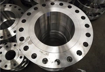
A WNRF flange manufactured in accordance with ASME B16.5, 12″ 900# SCH120, ASTM A105. The raised face is furnished with concentric serrated finish.
The facing finish or face finish of a pipe flange manufactured in accordance with ASME B16.5 refers to the smoothness or roughness of the facing surface. In a bolted flange joint, the flange face is in direct contact with the gasket. As the bolting is tightened, the softer gasket material flows into the minor machining imperfections of the flange facing, resulting in a fluid-tight seal. If the flange facing is smooth, a smaller tightening stress exerted on the bolting may result in an impervious seal. If the flange has a rough face, the smaller stress exerted may be inadequate to secure a tight joint. Less gasket flow in the flange joint will be necessary for the former than for the latter. Hence, the flange facing finish is an important factor in determining the extent to which a gasket must flow to secure an impervious seal.

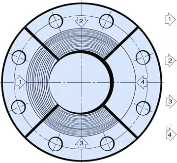
Different types of flange facing finishes: 1 – stock finish, 2 – spiral serrated, 3 – concentric serrated, 4 – smooth finish.
Typical facing finishes are defined in centerline average or roughness average Ra, which is the arithmetic average of the absolute values of the profile height deviations from the mean line. The facing finish of ASME B16.5 flanges shall be judged by visual comparison with Ra standards stipulated by ASME B46.1 and not by instruments having stylus tracers and electronic amplification. Generally, there are 4 types of facing finishes as illustrated in the above picture. Pipe flanges manufactured in accordance with ASME B16.5 may generally be furnished with 3 types of facing: raised face (RF), ring-type joint face (RTJ), and flat face (FF). The use of RTJ flanges always requires the use of a metallic ring gasket, which has a very smooth, mirror-like finish. The side wall surface finish of the gasket groove shall not exceed 1.6 μm [63 μinch] roughness. For FF and RF facing, either a serrated concentric or serrated spiral finish having a resultant surface finish from 3.2 μm to 6.3 μm [125 μinch to 250μinch] average roughness shall be furnished. The cutting tool employed should have an approximate 1.5 mm [0.06″] or larger radius, and there should be from 1.8 grooves / mm through 2.2 grooves / mm [45 grooves / inch through 55 grooves / inch].
The serrated finishes of ASME B16.5 flanges with RF or FF, either concentric or spiral, should be free of scratches or other imperfections to avoid radial leak paths. These imperfections in the flange facing finish shall not exceed the dimensions shown in the table below. A distance of at least four times the maximum radial projection shall separate adjacent imperfections. A radial projection shall be measured by the difference between an outer radius and inner radius encompassing the imperfection where the radii are struck from the centerline of the bore. Imperfections less than half the depth of the serrations shall not be considered cause for rejection. Protrusions above the serrations are not permitted.
| NPS | A | B |
|---|---|---|
| 1/2 | 3.0 | 1.5 |
| 3/4 | 3.0 | 1.5 |
| 1 | 3.0 | 1.5 |
| 1-1/4 | 3.0 | 1.5 |
| 1-1/2 | 3.0 | 1.5 |
| 2 | 3.0 | 1.5 |
| 2-1/2 | 3.0 | 1.5 |
| 3 | 4.5 | 1.5 |
| 3-1/2 | 6.0 | 3.0 |
| 4 | 6.0 | 3.0 |
| 5 | 6.0 | 3.0 |
| 6 | 6.0 | 3.0 |
| 8 | 8.0 | 4.5 |
| 10 | 8.0 | 4.5 |
| 12 | 8.0 | 4.5 |
| 14 | 8.0 | 4.5 |
| 16 | 10.0 | 4.5 |
| 18 | 12.0 | 6.0 |
| 20 | 12.0 | 6.0 |
| 22 | 12.0 | 6.0 |
| 24 | 12.0 | 6.0 |
