Categories
- Pipe & Tube (18)
- Flange & Fitting (97)
- Fastener & Gasket (12)
- Valve & Pump (18)
- Base Material (11)
- Equipment (8)
- Application (30)
- Technical (110)
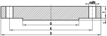
Blind flanges manufactured in accordance with ASME B16.5 can be provided in Class 150 through Class 2500. It is basically a circular disc that does not have a hub or bored center. Bolts holes are drilled and aligned symmetrically along the circumferential edge of the solid disc. Generally the blind flange may be furnished with raised face, ring join face, or flat face. The blind flange serves a function similar to that of a plug or cap and is used to blank off the end of piping, valves and pressure vessel openings. It may be fabricated from cast, forgings, specific plates, or flat bars.

Figure-1: a typical drawing for blind flange with raised face (RF) manufactured in accordance with ASME B16.5
Since it is bolted, the blind flange provides easy access to the interior of a vessel or pipe, unlike a cap that is welded. From the standpoint of internal pressure and bolt loading, blind flanges, particularly in large sizes, are the most high-stressed of all the standard flange types. However, since the maximum stresses in the blind flange are bending stresses at the flange center (that is robust enough to withstand the stresses), they can be safely permitted to be stressed more than other types of flanges.
If a blind flange is a tailor-made flange that doesn’t conform to ASME B16.5, it shall be designed in accordance with Section VIII, Division 1, UG-34 of ASME Boiler and Pressure Vessel Code, or ASME B31.3 para. 303 or para. 304.5. Design requirements of ASME Section VIII, Division 1, with allowable stresses from B31.3 are also referenced for the design of blind flanges.
In some cases, a threaded hole is required to be tapped in the center of the blind flange for inspection or vent purpose. The threaded hole may be tapped provided the flange is thick enough to allow the effective thread length specified in the table below. Otherwise, a boss shall be added for reinforcement. In no case shall the effective length of thread T be less than that shown in the table below. These lengths are equal to the effective thread length of external pipe threads in accordance with ASME B1.20.1. Generally, the 1/2″ tapping hole is most widely applied.
| *Size | *T |
|---|---|
| 3/8" | 10.5 |
| 1/2" | 13.5 |
| 3/4" | 14.0 |
| 1" | 17.5 |
| 1-1/4" | 18.1 |
| 1-1/2" | 18.3 |
| 2" | 19.4 |
| ASME B16.5 Blind Flanges, Classes | |||
|---|---|---|---|
| 150# | 300# | 400# | 600# |
| 900# | 1500# | 2500# | - |
As depicted in Figure-1, D: outside diameter of blind flange, K: diameter of bolt circle, G: outside diameter of raised face, T: minimum thickness of blind flange, n: number of bolts, d: diameter of bolt hole, t: height of raised face. The tolerances of basic dimensions of blind flanges are the same as that of slip on flanges.
