Categories
- Pipe & Tube (18)
- Flange & Fitting (97)
- Fastener & Gasket (12)
- Valve & Pump (18)
- Base Material (11)
- Equipment (8)
- Application (30)
- Technical (110)
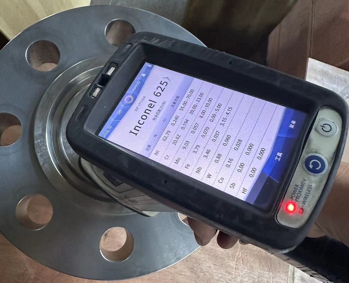
In order to enhance the corrosion resistance of the ring-type-joint (RTJ) sealing face of a carbon steel or low alloy steel flange, a layer or multiple layers of corrosion-resistant alloy Inconel 625 are deposited onto the surface of the RTJ groove of the flange through a arc welding process. The carbon or low alloy steel flanges are usually made of A105, A350 LF2, A182 F11, F5, F9, F91, A694 Gr.F52, F60, F65, F70, P250GH, P355NH, etc. The carbon or low-alloy steel base metal provides sufficient strength to sustain the design stress while maintaining cost-effective. Inconel alloy 625 (UNS N06625) is a Ni-Cr-Mo-Nb super alloy exhibiting high strength and excellent corrosion resistance in various harsh conditions such as high temperature and high pressure. However, Inconel 625 is very expensive. Large-size flanges made of homogeneous Inconel 625 is prohibitive. By depositing Inconel 625 weld overlays onto the wetted area (RTJ facing and bore diameter of flange), the superior corrosion resistance is imparted to the carbon or low-alloy steel main flange body.

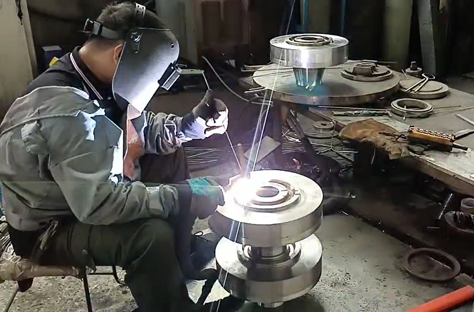
The gas tungsten arc welding (GTAW) process to overlay Inconel alloy 625 on to the RTJ facing of a welding neck flange. The welding is performed manually by a welder in our workshop.
The weld overlay of Inconel 625 can be done by submerged arc welding (SAW), gas tungsten arc welding / tungsten inert gas welding (GTAW/ TIG), and metal inert gas (MIG) welding. When applied to complicated RTJ facing overlay, TIG is often the best option. Conventional TIG can be done manually or automatically. Manual TIG welding can perfectly fit complicated surfaces of the workpiece. It also requires a high level of welder’s dexterity. Automated TIG gives the benefits of reduced heat input, stable arc, uniform weld profile and a spatter-free welding. The filler metal used in a TIG welding process is AWS A5.14 ERNiCrMo-3 (UNS N06625). The welding procedure specification (WPS) shall be qualified by the weld overlay testing of specimens as required by the ASME BPVC Code Section IX. The welding data for the test coupons and the results of the tests shall be recorded in a document called procedure qualification record (PQR). The welder or operator performance qualification is also required to prove the ability of the welder to make sound alloy 625 weld overlay and show if the operator can operate the welding equipment correctly.

ASME B16.5 4″ 2500# welding neck flanges with RTJ facing made of ASTM A694 Gr.65. Both the whole RTJ facing and bore diameter are weld overlaid by Inconel alloy 625. These flanges are supplied to a Petrobras project in Brazil.
The RTJ flanges with Inconel 625 weld overlay finds a very large application in Oil & Gas wellhead X-mas trees, especially in the search for and finds of oil and gas at great depth which features high pressure, high SO2 and CO2 contents, and very often elevated temperatures. They are also widely used in subsea and offshore marine piping systems where resistance to seawater corrosion is a key parameter. The Alloy 625 overlaid RTJ flanges also find extensive use in pressure vessels in coal-power plant’s flue gas desulfurization (FGD) process. With the improvement of technology and the reduction of production costs, alloy 625 weld overlay is increasingly applied in chemical, petrochemical, and other engineering services.

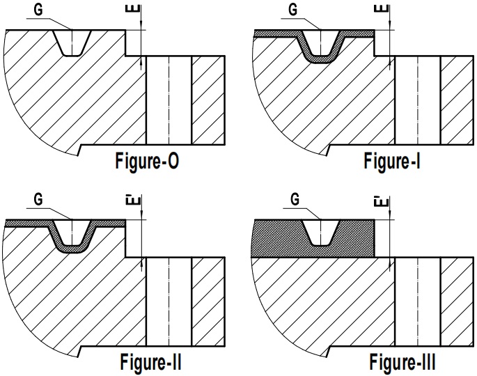
Dimensions and design of the RTJ flange facing, that is to be weld overlaid by Inconel 625 alloy.
Inconel alloy 625 is deposited onto the RTJ facing of the flange. The RTJ facing is furnished or machined out on the raised portion in addition to the flange thickness. The dimensions of the ring joint facing, as illustrated in position G of each figure, shall be in full conformance with those specified by ASME B16.5 or ASME B16.47. No matter how you change the welding process or the design of the raised portion, the groove G shall be kept identical, otherwise it cannot fit a metallic ring gasket made to ASME B16.20. Figure-O shows a homogeneous carbon steel flange with standard RTJ facing. The depth of the ring joint groove is E, which is equal to height of the raised portion. It is very important to note that according to Codes and Standards, the raised portion shall be furnished in addition to the minimum flange thickness. The weld overlaid deposits shall be viewed as a nonstructural component of the overall flange thickness. In Figure-I, the groove is extended in all directions on the basis of Figure-O to leave space for the welding deposit. The effective flange thickness has been reduced by the extension machining of the groove bottom. This is not a good practice and such a weld overlay design on the RTJ facing is not recommended. However, according to Article 305 Flange Repair and Conversion in ASME PCC-2, although the Figure-1 design has reduced the flange thickness, if the removal of the base metal does not compromise design integrity based on reevaluation as per Codes, such a design is still acceptable.

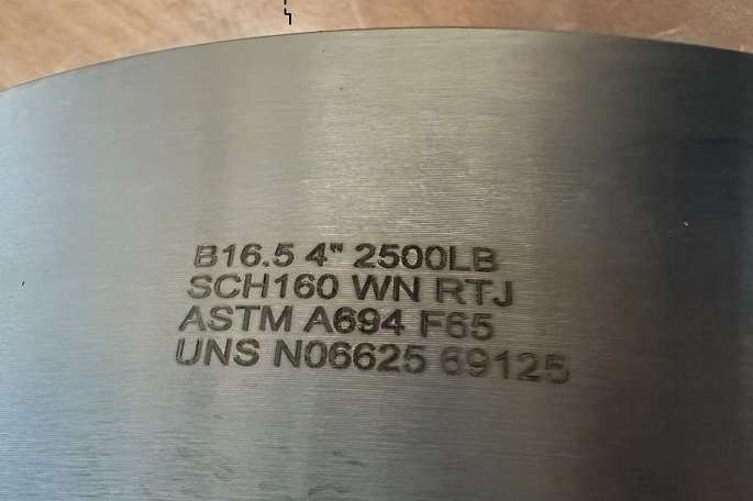
The standard marking for a WN flange made of ASTM A694 Gr.F65 with Inconel 625 weld overlaid RTJ facing.
In Figure-III, a standard flange with flat face (FF) made from base metal is provided. The raised portion in extended height E’ is weld overlaid as a whole onto the steel flange body. The groove as well as the facing surface are machined out subsequently. This design requires high volume of Inconel 625 alloy to be weld deposited hence is costly. Figure II provides the best solution: a standard carbon steel flange with a slightly longer raised portion, and the ring-joint groove is initially machined larger than the standard for subsequent weld deposition. After multi-layers weld overlay of Inconel alloy 625, precision machining on CNC lathe is then performed to get the final RTJ facing. In this case, longer studs shall be used for flange installation.
