Product Categories
- Products (61)
Universal type spherical rubber expansion joints, single sphere, double floating flanges (stainless steel 304), supplied to Riyadh, Saudi Arabia.
The universal flanged type spherical rubber expansion joint is the most commonly used non-metallic expansion joint, which has a single-sphere or double-sphere shaped arch to absorb movements and vibration effectively. It consists of two parts: two floating metallic flanges and a rubber bellows. The two metallic flanges act as the end connector, which will be bolted up with piping flanges in the system. They shall have a groove to accept the beaded end of the rubber bellows. The rubber bellows is made of natural rubber or synthetic rubber, reinforced with multiplies of woven fabrics or tire cord impregnated with rubber. Additional reinforcement to the fabric may be steel wires imbedded in the rubber. The beaded end of the bellows works as a sealing gasket between mating flanges.
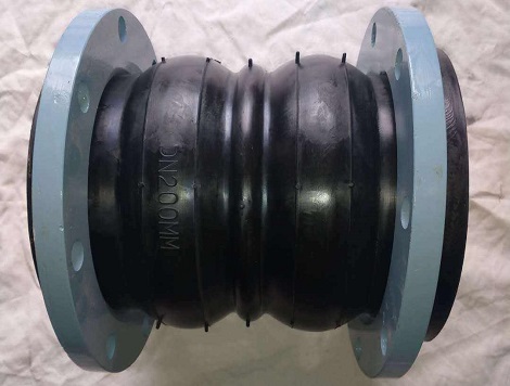
A twin-sphere rubber expansion joint, DN200 PN16, natural rubber bellows, A105 flanges powder coated.
The rubber bellows is composed of inner tube (which is in contact with the flowing media), cover (the exterior surface of the expansion joint), carcass (the supporting framework in between the cover and the tube). The tube, cover and carcass are brought up from the bellows body to form a bead. In the middle of the spherical rubber bellows, a long-radius arch is formed. The spherical contour prevents sediment accumulation and creates less turbulence and pressure drop than small-radius or straight arches. Since the uniform pressure distribution throughout the arch wall, the long-radius sphere is inherently robust and provides resilient sealing during the lifespan of the joint. Double spheres have similar construction and performance, but to provide greater movement & vibration absorption. An extra reinforcing root ring is usually furnished between the two spherical arches.
The universal flanged type spherical rubber expansion joints, either single sphere or double sphere, are widely used for the absorption of movements and vibration or sound dampening in piping applications. These joints are commonly installed as pump and equipment connectors to acoustically isolate rotating equipment from system piping. They generally provide designed compensation for axial compression, axial extension, lateral deflection and angular deflection in piping systems. The flanges of the joint may be made from carbon steel (painted, hot-dipped galvanized) or stainless steel (Type 304 & Type 316). The rubber bellows may be made from natural rubber, EPDM, Hypalon, Neoprene, Buna N (NBR), Viton (FKM), EPDM+PTFE. The woven fabric or tire cord for reinforcement shall be nylon, polyester, fiberglass, or aramid.
| Specification of Rubber Expansion Joints | ||
|---|---|---|
| Single Sphere | Twin Sphere | Union Spherical |
| Spool Arch | Tie Rods | Special Design |
| Flange Drilling | Installation & Maintenance | Testing & Inspection |
The manufacture of the universal flanged type spherical rubber expansion joint involves the fabrication of the rubber bellows and the manufacture of the metallic flanges. The flanges can be made by a forging or casting process with proper machining performed. The make of the rubber bellows is the critical process in the manufacture of the expansion joint. It involves several major processes: compounding, mixing, calendering, shaping, and vulcanising. After the rubber bellows is completed, the two flanges shall be installed onto each end to finish the assembly. The expansion joints shall be examined and tested, and subsequently packaged and stored. The manufacture of the rubber bellows from scratch is introduced in the following pictures.
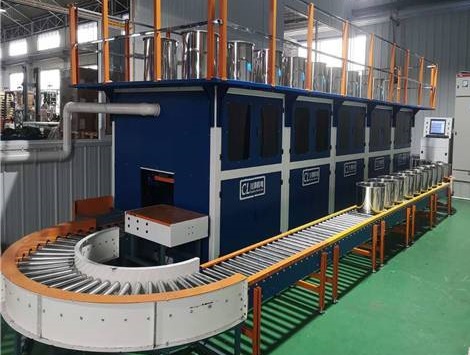
The rubber compounding system.
Compounding: The rubber compounding process is the design and engineering of rubbers and rubber additives such as fillers, vulcanising agents, vulcanisation accelerators, activators of vulcanisation, retarders and inhibitors of vulcanisation, anti-degradants, anti-reversion agents, plasticisers and softeners, and miscellaneous ingredients. The compounding ingredients for inner tube, cover, and carcass of the expansion joints shall be engineered respectively to meet various service conditions and requirements.
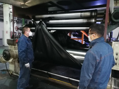
The mixer for rubber mixing process.
Mixing: Since the gum rubber is elastic, it cannot be conveniently formed or shaped into desired workpiece. The mixing process involves the mastication of the rubber, as well as the addition of various additives and fillers. When the rubber is forced through the two-roll mill, it becomes soft and tacky, and additives and fillers are distributed uniformly in the masticated rubber. Due to the improved plasticity, rubber bellows can be easily built up from multiple pieces of the masticated & mixed rough rubber sheet. Sheets of precision thickness can be obtained by the calendering process, in which rubber is impregnated with the nylon or polyester tire cord to prepare starting materials for the joint carcass.
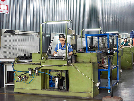
The shaping and forming of rubber bellows on a spinning mandrel.
Shaping: The spherical-arch type rubber bellows are formed by winding multiple pieces of unvulcanized rubber sheets on to a spinning mandrel (die mold). The inner tube, carcass, and cover of the bellows are formed sequentially by wrapping multiple plies of respective rubber sheets.
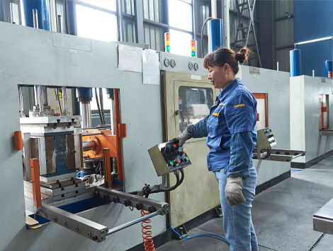
The vulcanization of rubber bellows for the expansion joints. Automated vulcanisation production line.
Vulcanising: The final step in the manufacturing sequence is vulcanisation of the shaped bellows. Basically, the vulcanisation is carried out by heating at an elevated temperature for a predetermined period of time. It transforms the linear polymer into a three-dimensional macromolecule by the insertion of a relatively few crosslinks between the rubber polymer chains. After the vulcanizing or curing process, the rubber bellows becomes elastic and robust, and suitable for movements- & vibration-absorption.
| NPS | L inch | L1 inch | L2 inch | L3 inch |
|---|---|---|---|---|
| 1.25" | 6 | 0.500 | 0.375 | 0.500 |
| 1.5" | 6 | 0.500 | 0.375 | 0.500 |
| 2" | 6 | 0.500 | 0.375 | 0.500 |
| 2.5" | 6 | 0.500 | 0.375 | 0.500 |
| 3" | 6 | 0.500 | 0.375 | 0.500 |
| 4" | 6 | 0.625 | 0.375 | 0.500 |
| 5" | 6 | 0.625 | 0.375 | 0.500 |
| 6" | 6 | 0.625 | 0.375 | 0.500 |
| 8" | 6 | 0.625 | 0.375 | 0.500 |
| 10" | 6 | 0.750 | 0.500 | 0.750 |
| 12" | 8 | 0.750 | 0.500 | 0.750 |
| 14" | 8 | 1.000 | 0.625 | 0.750 |
| 16" | 8 | 1.000 | 0.625 | 0.750 |
| 18" | 8 | 1.000 | 0.625 | 0.750 |
| 20" | 8 | 1.000 | 0.625 | 0.750 |
| 24" | 10 | 1.000 | 0.625 | 0.750 |
| NPS | A ° | P1 psig | P2 inch Hg | W lbs |
|---|---|---|---|---|
| 1.25" | 31 | 225 | 26 | 5.0 |
| 1.5" | 27 | 225 | 26 | 6.0 |
| 2" | 20 | 225 | 26 | 9.0 |
| 2.5" | 17 | 225 | 26 | 12.0 |
| 3" | 14 | 225 | 26 | 14.0 |
| 4" | 14 | 225 | 26 | 18.0 |
| 5" | 11 | 225 | 26 | 22.0 |
| 6" | 9 | 225 | 26 | 27.0 |
| 8" | 8 | 225 | 26 | 40.0 |
| 10" | 7 | 225 | 26 | 56.0 |
| 12" | 6 | 225 | 26 | 83.0 |
| 14" | 5 | 150 | 20 | 115 |
| 16" | 4 | 125 | 20 | 165 |
| 18" | 4 | 125 | 15 | 168 |
| 20" | 3 | 125 | 15 | 170 |
| 24" | 3 | 110 | 15 | 255 |
| NPS | L inch | L1 inch | L2 inch | L3 inch |
|---|---|---|---|---|
| 2" | 7 | 2.000 | 1.000 | 0.500 |
| 2.5" | 7 | 2.000 | 1.000 | 0.500 |
| 3" | 7 | 2.000 | 1.000 | 0.500 |
| 4" | 9 | 2.000 | 1.375 | 0.500 |
| 5" | 9 | 2.000 | 1.375 | 0.500 |
| 6" | 9 | 2.000 | 1.375 | 0.500 |
| 8" | 13 | 2.375 | 1.375 | 0.500 |
| 10" | 13 | 2.375 | 1.500 | 0.750 |
| 12" | 13 | 2.375 | 1.500 | 0.750 |
| 14" | 13.75 | 2.375 | 1.500 | 0.750 |
| NPS | A ° | P1 psig | P2 inch Hg | W lbs |
|---|---|---|---|---|
| 2" | 45 | 225 | 26 | 9.2 |
| 2.5" | 43 | 225 | 26 | 13.0 |
| 3" | 38 | 225 | 26 | 15.0 |
| 4" | 34 | 225 | 26 | 20.0 |
| 5" | 29 | 225 | 26 | 25.0 |
| 6" | 25 | 225 | 26 | 30.0 |
| 8" | 19 | 225 | 26 | 44.0 |
| 10" | 15 | 225 | 15 | 66.0 |
| 12" | 13 | 225 | 15 | 95.0 |
| 14" | 12 | 150 | 15 | 124 |
The flange drilling dimensions shall be furnished in accordance with a series of national and international standards covering HG/T, GB, BS 4504, BS 10, BS 3293, JIS, DIN, AMSE B16.5, ASME B16.1, ASME B16.24, ASME B16.47, AWWA C-207, EN 1092-1, GOST, AS 2129, etc.
