Categories
- Pipe & Tube (18)
- Flange & Fitting (97)
- Fastener & Gasket (12)
- Valve & Pump (18)
- Base Material (11)
- Equipment (8)
- Application (30)
- Technical (110)
The threaded flange manufactured in accordance with ASME B16.5 is similar to the slip on flange, but the bore shall have a taper pipe thread conforming to ASME B1.20.1. The thread shall be concentric with the axis of the flange opening, and variations in alignment (perpendicular to the flange face) shall not exceed 5 mm per meter. Threaded flanges are available in sizes NPS 1/2 through NPS 24 for pressure ratings of Class 150, Class 300, Class 400, Class 600 and Class 900. Sizes for Class 1500 and Class 2500 are available from NPS 1/2 to NPS 2-1/2.

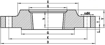
The drawing for a threaded flange conforming to ASME B16.5. The counterbore indicates that it is a Class 300 or higher pressure rating.
Class 150 threaded flanges are made without a counterbore. The threads shall be chamfered approximately to the major diameter of the thread at the back of the flange at an angle of approximately 45 deg with the axis of the thread. The chamfer shall be concentric with the thread and shall be included in the measurement of the thread length. Class 300 and higher pressure class flanges shall be made with a counterbore at the back of the flange. The threads shall be chamfered to the diameter of the counterbore at an angle of approximately 45 deg with the axis of the threads. The counterbore and chamfer shall be concentric with the thread.
Internal threads of flanges shall be checked with gages having a gaging notch. Variations in threading shall be limited to one turn large or one turn small from the gaging notch when using working gages. The reference point for chamfered thread (Class 150) gaging is the starting end of the threaded flange, provided the thread chamfer does not exceed the major diameter of the internal thread. When a chamfer on the internal thread exceeds this limit, the reference point becomes the last thread scratch on this chamfer cone. The reference point for counterbored thread (Classes 300 through 2500) gaging shall be the last thread scratch on the chamfer cone.
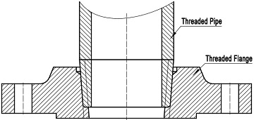
The threaded flange joint can be assembled without welding. A pipe, which is furnished with tapered threads at its ends, can be readily assembled with the threaded flange. This feature makes the threaded flange well-suited to extreme pressure services that operate at normal ambient temperatures and in highly explosive areas where welding may create a hazard.

Connecting a pipe to the threaded flange.
The disadvantages of threaded flanges are also obvious. The crevices formed between the external and internal threads may easily capture and retain process fluid. This makes the threaded connection susceptible to crevice corrosion during which process fluid penetrates the thread region and results in failure. The threaded joints also represent significant stress risers. Since stress is drastically intensified in the thread region due to tightening, a relatively few cycles of expansion and contraction or movement caused by misalignment may subject the threaded flange to failure.
Threaded steel flanges are usually limited to water or air services for sizes NPS 6 (DN 150) or smaller and with design temperature not exceeding 250°F. They are not suitable for conditions involving high temperatures, cyclic stresses, or corrosive fluid. The dimensional tolerances of threaded flange are almost the same as that of slip on flanges. Additionally, tolerances for threaded flange counterbores are as follows: for NPS ≤ 10, +1.0 mm to -0.0 mm; for NPS ≥ 12, +1.5 mm to -0.0 mm.
| ASME B16.5 Threaded Flange, Classes | |||
|---|---|---|---|
| 150# | 300# | 400# | 600# |
| 900# | 1500# | 2500# | - |
